2007 Revell Raider - Build Diary
Posted: Sun Feb 22, 2009 3:57 pm
Alright all you tin cans, here is the start of my 2007 Revell Raider build. I decided to go ahead and light the engines to take advantage of the new parts this kit had to offer.
Let the carnage begin!
Okay, so I'm a Cylon - AND I HAVE A PLAN
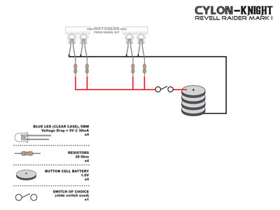
My first (and hopefully working) electric circuit plan.
Well plans are made to fall apart . When I went Radio Shack (to impatient to order the stuff online to save a few dollars) they didn't have the correct resistors in stock. I needed 39 Ohm resisters.
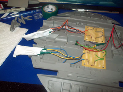
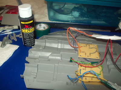
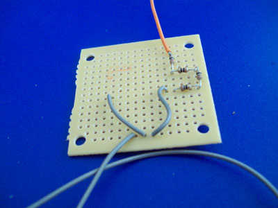
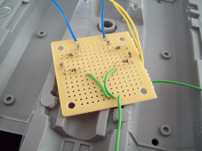
  I found they had 10 Ohm ones so I bought them - hoping that I could wire them in sequence to get 40 Ohms in the end for each light. I looked it up and turns out you can - so cool. At this point "1 Ohm less" per light is something I was starting to care less about. SO - This photo has the gray wires as positive coming into the circuit, then going to the fraking four resistors in place of one per light, the orange wire goes off to the LED.
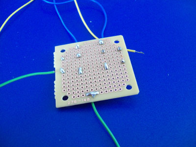
I found a neat little PC board that could be snapped in half, so I got that for ALL of my resistors. Here is the bottom of one of them. I guess that the need for 16 resistors in place of 4 was sort of a blessing for my learning. I had much more to solder - with my new soldering gun .
.
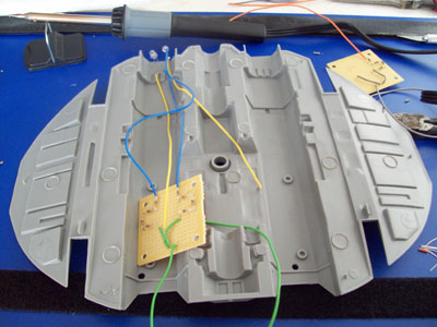
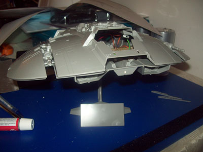
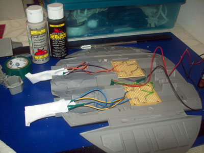
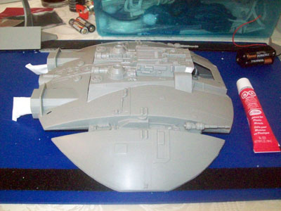
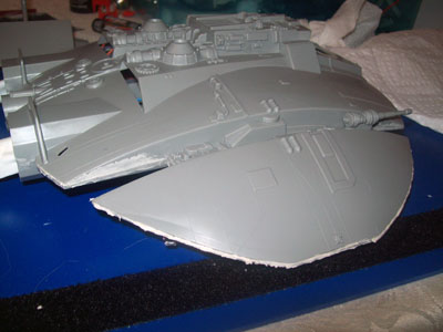
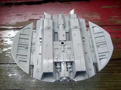
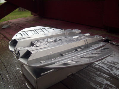
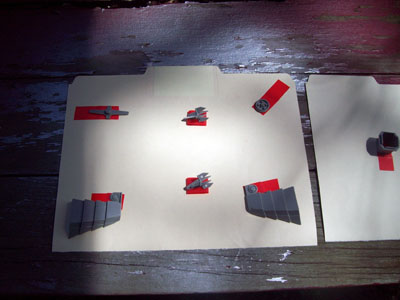
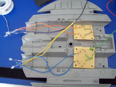
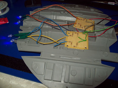
Enter the lower hull. You can see the build taking shape.
(YES, for the eagle-eye Cylons out there I have something like 8 colors of wires going. I salvaged them from a clunky Knight Rider light bar that I'm dissecting off-and-on to see how its circuit was designed. All the colors made it a easier for this first wiring project to keep everything going where it should.)
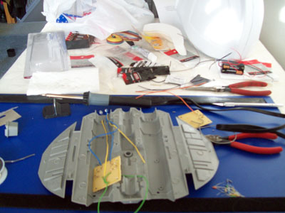
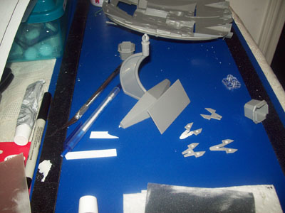
Oh my... what a messy work area. BUT invention, my dear friends, is 93% perspiration, 6% electricity, 4% evaporation, and 2% butterscotch ripple. (Willy Wonka quote LOL.)
P.S. Did you eagle-eyes notice the white Cylon Helmet project at the top right?
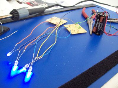
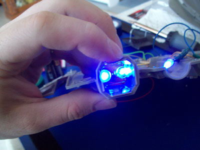
IT'S ALIVE! *forgive me, having a Frankenstein moment*
Powered up and glowing Seems like everything is working, nothing exploded... that's good. The AAA batteries are just for testing. I plan on using button cell batteries in the final setup (per THE PLAN).
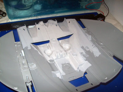
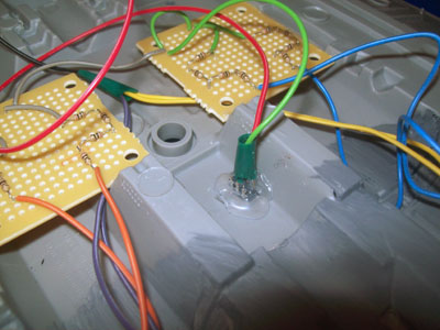
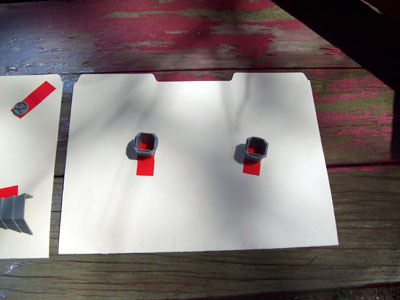
Both PC boards on the lower hull. Trying to figure out how everything is going to fit inside.
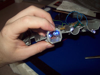
Close up of the starboard side electronics.
OKAY - I'm know it is laughably over-complex, and it could be more compact. But when I close up the hull no one will know.
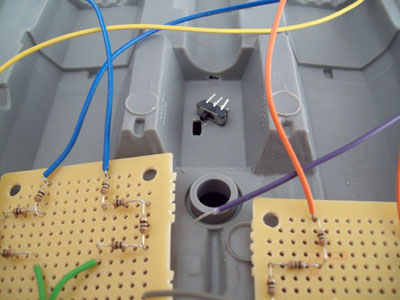
Now, I need an on off switch. So here it is, to the lower left of it is the hole I cut for it to mount through.
(Note the failed mounting hole above the switch. Turned out the details on the outside of the hull were in the way for the switch to fit right. That's why the Imperious Leader gave us Centurions model putty.)
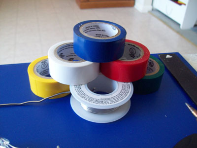
Whee - having too much fun with my new colored electrical tape and solder. Guess what color of tape I used and win $5 (JUST KIDDING).
Everything tapped up now - ready to start gluing in the boards. If you guessed green for the tape, pat yourself on your Cylon backpack. (Green for the Cylon Empire logo color.)
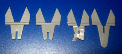
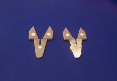
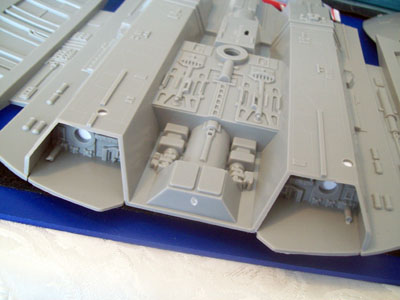
Testing the lights in the engine assembly. (This photo no flash)
(This photo with flash)
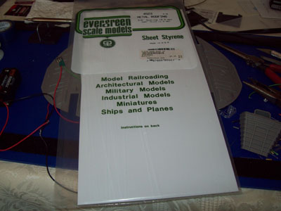
At this point I decided that I'd use the AAA batteries - the button cells were way expensive at the store. This sheet styrene is for my Cylon Helmet... to put on the inside of the mohawk and help hold the two halves together. I decided to use a section of it to make a brace for the AAA's to hang from the upper hull.
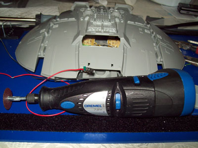
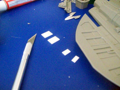
*Evil Laughter* THE DREMEL!
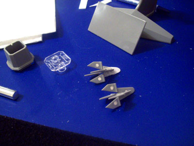
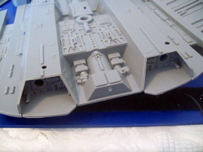
The hull will be glued shut and puttied. I need to open up the hole under the canopy to allow access to the AAA pack. The Canopy will be 'loosely' installed in my final model for the day the batteries finally give out.
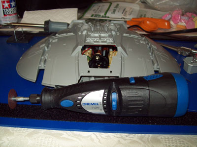
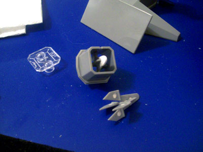
Cutting complete. Now the AAA pack can be taken in/out with ease. The brace to hang it from flopped... I settled for it just sitting in the center of the ship, that will be good enough. Button cells would be ideal, but the cost of that and everything else - it winds up costing more than the Raider itself, so I am staying with AAAs.

See you next time for "Painting with Cylon-Knight"
Everyone get their Raiders ready!
Let the carnage begin!
Okay, so I'm a Cylon - AND I HAVE A PLAN
My first (and hopefully working) electric circuit plan.
Well plans are made to fall apart
I found a neat little PC board that could be snapped in half, so I got that for ALL of my resistors. Here is the bottom of one of them. I guess that the need for 16 resistors in place of 4 was sort of a blessing for my learning. I had much more to solder - with my new soldering gun
Enter the lower hull. You can see the build taking shape.
(YES, for the eagle-eye Cylons out there I have something like 8 colors of wires going. I salvaged them from a clunky Knight Rider light bar that I'm dissecting off-and-on to see how its circuit was designed. All the colors made it a easier for this first wiring project to keep everything going where it should.)
Oh my... what a messy work area. BUT invention, my dear friends, is 93% perspiration, 6% electricity, 4% evaporation, and 2% butterscotch ripple. (Willy Wonka quote LOL.)
P.S. Did you eagle-eyes notice the white Cylon Helmet project at the top right?
IT'S ALIVE! *forgive me, having a Frankenstein moment*
Powered up and glowing
Both PC boards on the lower hull. Trying to figure out how everything is going to fit inside.
Close up of the starboard side electronics.
OKAY - I'm know it is laughably over-complex, and it could be more compact. But when I close up the hull no one will know.
Now, I need an on off switch. So here it is, to the lower left of it is the hole I cut for it to mount through.
(Note the failed mounting hole above the switch. Turned out the details on the outside of the hull were in the way for the switch to fit right. That's why the Imperious Leader gave us Centurions model putty.)
Whee - having too much fun with my new colored electrical tape and solder. Guess what color of tape I used and win $5 (JUST KIDDING).
Everything tapped up now - ready to start gluing in the boards. If you guessed green for the tape, pat yourself on your Cylon backpack. (Green for the Cylon Empire logo color.
Testing the lights in the engine assembly. (This photo no flash)
(This photo with flash)
At this point I decided that I'd use the AAA batteries - the button cells were way expensive at the store. This sheet styrene is for my Cylon Helmet... to put on the inside of the mohawk and help hold the two halves together. I decided to use a section of it to make a brace for the AAA's to hang from the upper hull.
*Evil Laughter* THE DREMEL!
The hull will be glued shut and puttied. I need to open up the hole under the canopy to allow access to the AAA pack. The Canopy will be 'loosely' installed in my final model for the day the batteries finally give out.
Cutting complete. Now the AAA pack can be taken in/out with ease. The brace to hang it from flopped... I settled for it just sitting in the center of the ship, that will be good enough. Button cells would be ideal, but the cost of that and everything else - it winds up costing more than the Raider itself, so I am staying with AAAs.
See you next time for "Painting with Cylon-Knight"
Everyone get their Raiders ready!